Design and simulation of Coriolis based gyroscopes
Lumped mass gyroscope and accelerometer with resonant sensing
The structure of the integrated in-plane(y) & out-of-plane(z) accelerometer and of the roll & yaw gyroscope comprises 2 proof masses for differential measure, 4 torsional resonators and 4 beam flexional resonator
.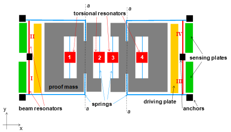
Plan view of the structure
The beam resonators I, II, III e IV allow for the differential sensing of in-plane acceleration ay, and yaw Wz, the torsional resonators 1, 2, 3 and 4 allow for the differential sensing of out-of-plane acceleration az, and roll Wy.
The two proof masses are driven to resonance in the x direction through electrostatic actuation.
External angular velocities induce Coriolis’ forces, causing unsymmetric movement of the two masses, while external accelerations induce inertia forces, causing symmetric movement of the two masses. These movements generate axial forces in beam resonators, thus changing their frequency, or a variation in the gap between torsional resonator and substrate, that changing their frequency.
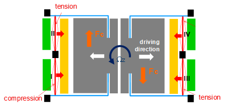
Scheme for the detection of the yaw Wz
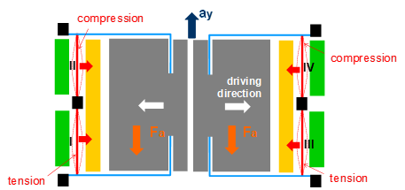
Scheme for the detection of the acceleration ay
One can de-couple the effect of acceleration from that of angular velocity by properly combining the resonators signals.
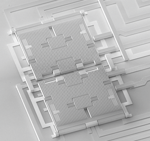
SEM image of the 4 axis gyroscope-accelerometer
Disc resonator gyroscope
The disc resonator gyroscope studied, takes advantage of the symmetric structure and central anchor of a ring, but the mass is increased by adding concentric internal rings. The device is realized by a single-crystal silicon slotted disc supported by a central cylindrical anchor and surrounded by capacitive electrodes used to force and sense vibration; it has orthogonal flexural elliptical modes, separated by 45?.
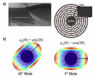
Disc resonator gyroscope: (a) SEM of disc resonator gyroscope and drawing of disc resonator gyroscope shape, with inset SEM of rings; (b) orthogonal elliptical mode shapes, with contours of displacement. Source: Nitzan et al. (2015)
Frequency modulated gyroscopes
Frequency-modulated (FM) MEMS gyroscopes have been proposed as a valid alternative to their amplitude-modulated (AM) counterparts in order to achieve high scale factor stability against fabrication imperfections and environmental fluctuations.
Innovative mechanical designs of the first single mass and dual mass FM pitch gyroscopes have been proposed by our group and the first three-axes FM gyroscope have been deposited for a patent.
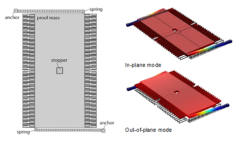
Mechanical design of the Lissajous Frequency Modulation (LFM) – single mass pitch gyroscope.
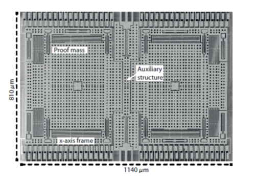
SEM image of the dual-mass pitch FM gyroscope
 a) In-plane mode and b) Out-of-plane mode of the pitch FM gyroscope
